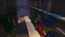
Der Schmale – David Lenaerts’s blog

Flash Platform Experiments

Convolution Light Probes in Away3D 4.0

Tags: , , , ,

As mentioned in the previous blog post, the dev branch of Away3D 4.0 now has light probes. Light probes are essentially a special sort of light source that contain global lighting info for the scene location they’re placed at, encoded as cube maps. For diffuse lighting, these cube maps are simply indexed by the surface normal of the shaded fragment. For specular lighting, the view reflection vector is used. As such they’re a fast basic way of faking global illumination. The fact that it’s using cube maps means that the lighting would only be physically correct at the precise point where the light was sampled, but the results can still be convincing regardless. Several light probes can be placed in a scene; the material’s light picker will assign weights to each to determine the importance in the lighting step based on the rendered object’s position relative to each.

You can use normal lights alongside the light probes, and in case of the default material system, you can specify which lighting component (diffuse and specular) is affected by which light types (material.diffuseLightSources and material.specularLightSources accepting LightSources.LIGHTS, LightSources.PROBES,  or LightSources.ALL). This can be useful if you want to use light probes for diffuse global lighting, but want specular lights from traditional light sources without those affecting the diffuse light.


Pre-process step

A downside of this approach over conventional light sources is that it requires a pre-process step to generate the cube maps. To start with, you need to generate (HDR) cube map renders for every point where you’ll want to put a light probe. From this, two process steps can be applied: a diffuse convolution and a specular convolution, depending on which type of lighting the probe needs to support. These can be generated in the eminent Paul Debevec’s HDRShop. I’ll warn you, however, that these convolutions can be very time-consuming – but the results are very accurate. If you’re willing to sacrifice some accuracy and get your hands dirty, you can write your own “convolutor”. Be warned however, that Flash doesn’t support HDR in BitmapData or textures, so if you’re using BitmapData and Stage3D, you’ll end up with under-lit results due to the low dynamic range of “bright” light. Having said that, I’ll quickly outline the principles behind it, just in case it interests anyone.

Lighting functions are spherical functions (the domain is the unit sphere, being mapped to scalar values), so you’ll need to integrate the diffuse or specular lighting function over the unit sphere of surface normals/view reflections. In fact, integrating over the hemisphere is usually enough since there’s no light coming from inside objects in our case. But as I was lazy and it was much easier to just implement it for the entire sphere I’ll use that approach ;) For basic (Lambertian) diffuse reflections, this semi-formally boils down to:

Where N is the surface normal, “ω_i” is the incident light vector, and L(ω_i) is the light colour coming from the direction ω_i. The part “max(N.ω_i, 0) L(ω_i)”, is in fact just the same as the diffuse lighting calculation done for point and directional lights (where L is a constant function). In this case, L(ω_i) is simply a sample from the HDR cube map we rendered before. The integral just means that we’re taking the diffuse contributions for all directions (ie: all vectors ω_i in the unit sphere S) and accumulating them. Finally, to be able to sample the incoming light for each normal in an environment map, we would need to perform this calculation for every point in that map (remember, cube maps coordinates are simply 3D vectors, in this case representing the surface normal N).

In theory, the integral means we’d be summing up infinite amounts of infinitesimal samples. In practice, we’ll be using discrete steps to solve this. That’s okay, since we only have finite amount of samples to work with anyway; 6*n² pixels to be exact, n being the size of the HDR cube map. So, the most accurate way of doing things would be to add up all the contributions from the source map, and do that for each pixel in the destination map. If we’re rendering to a cube map of size m, that means it’s an order of 6*m² * 6*n² = 36m²n² (6 sides of m*m, each pixel sampling 6 sides of n*n). This can easily become a very expensive operation. Luckily, there are some numerical methods to solve this faster (at the cost of accuracy, or what did you expect). The most useful in this case is definitely Monte Carlo integration, which allows less samples from the source material per pixel. There are many articles written about the subject, and a great introduction is found in this article by Robin Green.

Enough to get you cracking, I think ;)


Demo

See the Cornell Boxness of it all!

Use the arrow keys to move the head, space bar to toggle the texture (shows the lighting impact), and finally click and drag to rotate the head.

The head model and textures are still by Lee Perry-Smith (who by now must feel pretty awkward appearing in random tech demos). Source for the demo can be found in the texture-refactor branch of the examples repo (which will be merged to master together with the dev branch).

The environment maps were made as outlined before using a custom generation tool, and placed close to each corner of the box where they were generated.  I was using Stage3D (and thus a low dynamic range) to generate them, so I had to do some touch-ups in Photoshop to get them to look right. I’m not done investigating the options for further development of such map generation tools, but who knows they’ll make it public some day. In any case, HDRShop is more reliable! Diffuse lighting is set to use light probes only, while specular lighting uses the point light only.

The demo also shows how to use point light shadows, rim lighting and light mapping for added static shading.

Leave a comment (6 comments)

Hacking the Lite pt.2: Fake Shadow Mapping

Tags: , , , , , , , , , ,

fakeShadowsSince I’ve been working on Away3D 4.0 (Broomstick) for the past few months, it was pretty hard to find the energy to keep this blog up to date, and the promised part 2 of Hacking the Lite kept getting delayed. And delayed. And then delayed some more. Having access to the GPU also caused some debate on whether this series would still be relevant enough. However, after looking at my initial goals for it, I decided it is. After all, the idea was to inspire people to start playing around, and to get people to think in terms of using shaders. Most of the concepts outlined here can be used in Molehill as well. And of course, it’s still some time before we can use the GPU in actual commercial projects ;) So on with the show! This part of the series will build heavily upon the previous part, so it’s perhaps a good idea to review that again.

Shadow maps

Casting shadows is often done using shadow maps. In this case, we’d render a “depth map” of the scene from the light’s point of view. This way, we have a texture containing the distances to the objects closest to the light for every projection ray (which is a single pixel in the shadow map). When rendering the scene, we project every point we are rendering to that shadow map. We can then compare the depth value of the point-to-be-rendered with the value in the shadow map. If it is further away from the light, it must be in shadow and should not be lit. This approach works well, but for current versions of Flash, it’s not very feasible. But, since we’re hacking, there’s other options!

Augmenting projective texture mapping

fakeShadowMapping_thumbIf you take a look at the schematic on the left (click to enlarge), showing where a shadow should fall, you can see it’s much like projection mapping. The sphere is being perspectively projected unto the floor plane with the light as the projection’s origin. This is the exact same projection that projects the light texture onto the objects. As you can see, if we project the sphere onto the light’s texture first, and project that in turn to the floor, the shadow region remains the same. As a result, we could actually simply project and draw the sphere into the light map before it is applied to the floor.

Order and form

shadowOrderTo render a scene with multiple objects, we have to take care to render things in correct order. We need to draw the objects closest to the light first, because they will obviously be casting shadows on object further from the light. Starting out with a clean light map (ie.containing no shadows), we project it on the closest object and then draw that object’s shadow into the light map. Move on to the second closest object, light it, and draw the shadow again. And so on until the last object was reached.

That works great for convex objects, as long as they don’t intersect. For concave or intersecting convex objects, it’s possible that object A casts shadows on object B as well as the other way around. Since we’re rendering everything in a strict order, that’s simply not a possibility. However, this error should generally be acceptable. Another problem is self-shadowing for concave objects, which is impossible using this “cheat”.

Demo and source

Fake shadow mapping demo: really just an adapted version of the previous one.

The source is again on Google Code!

Leave a comment (2 comments)

© 2009 Der Schmale – David Lenaerts’s blog. All Rights Reserved.

This blog is powered by Wordpress and Magatheme by Bryan Helmig.