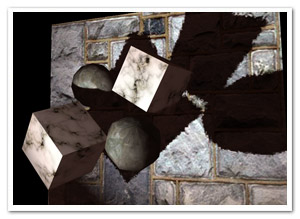
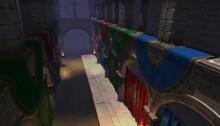
Der Schmale – David Lenaerts’s blog

Flash Platform Experiments

Building efficient content in Away3D 4.0: Sharing Materials & Geometries

Tags: , , , , , , , ,

Time to dig deeper into Away3D 4.0 and see how you can structure and manage your content to get the best performance! If you haven’t read the previous posts, it wouldn’t hurt to do so now, since this one will be all about Materials (on the Mesh side of things) and Geometries.

In any sort of project, if you have data collections that use a lot of memory, it makes sense not to duplicate them if you want to share the same data across several clients (clients simply meaning “users of the data”). Instead, you make all clients refer to the same data object, or model. Similarly, you probably wouldn’t want to perform the same expensive operations on this data for every client. The shared model can take care of that only once for all clients. In the Away3D scene graph structure, the Geometry is essentially your model, and a Mesh refers to it. Many Meshes can make use of the same Geometry. Similarly, Materials can be shared across Meshes as well. This all sounds very logical, yet for some reason I can’t fathom, this is a principle that’s often violated against. Even though Away3D internally tries to minimize memory use and tries to share things as best as it can (it caches Program3D instances, Texture objects, etc., across material instances), I can’t stress this enough: reuse Material and Geometry instances whenever possible. Not only does it limit CPU and GPU memory usage, it’s also essential for performance. I’ll explain why.

Reusing Materials

Every material uses a “shader program”, which is represented in Actionscript by a Program3D object. It’s a combination of a vertex shader and a fragment shader. I won’t go into the subject of shader programs in detail, but if you’re interested, check wikipedia for starters. A large task of the shader program is to define the colour of every pixel that’s being drawn. In other words, it controls how your rendered object will be coloured, textured, lit, shaded, … If it’s on your screen, it passed through a shader program. As a result, a different material means it needs a different Program3D. When drawing objects, the gpu needs to be told to use a different program every time for every material. Unfortunately, this switch is typically very expensive and something you’d want to prevent as much as possible. To this end, Away3D sorts all the objects that need to be rendered (the so called “renderables”) primarily according to their materials so all objects with the same material will be rendered consecutively. If you’re using different material instances for things that look exactly the same, it means more programs need to be switched needlessly.

Sharing materials allows more renderables (here SubGeometry objects) to be rendered with less switches

Sharing materials allows more renderables (here SubGeometry objects) to be rendered with less switches

Okay, I’ll admit, that isn’t entirely true. For those interested, I’ll explain what really happens. Whenever a material is created or changed so that it needs to create a new shader program, the vertex and fragment code is regenerated. A Program3D is requested from a central cache, but if a Program3D object already exists for that exact code combination, the existing object is returned. Different materials using the same code also use the same programs, which means there won’t be any program switching. However, it’s easy enough to accidentally have small differences between materials so that the code – and in turn the program instance – changes. And the following is still true regardless:

Every time a material changes, certain data needs to be uploaded to the GPU: Textures, lighting properties, … No caching of Program3D objects is going to prevent that. If you use a new material instance for every object, these uploads may occur for every object. Share a material, and it only happens once for all the renderables using it.

Note: if you really need several material instances, but you’re using the same BitmapData objects as textures or normal maps, at least try to share those across materials unless you have a very good reason not to. RAM’s not for wasting! Furthermore, there’s a limit to the amount of Texture objects (a buffer object representing the image data on the GPU) that can be created, and for every BitmapData, a Texture is created. You wouldn’t want to go over the limit!

Reusing Geometries

Similarly, Meshes that use the same data should all refer to a single Geometry instance. A very common example is a game in which there are several occurences of the same monster type spread throughout the game map. You can have one “beer demon” Geometry, and place many beer demons in your level by making the different Mesh objects refer to that single Geometry instance. Not only does this use much less memory, it also causes less instances of VertexBuffer3D to be created (these are buffers representing the vertex data on the GPU side of things). There’s a limit on how many can exist at any given time and if you exceed it, an error will be thrown and your game will crash. Sharing Geometry objects can also result in better performance in some cases, because if the same Geometry was used for the previously rendered object, it may not have to reupload its data to the GPU!

Material/Geometry Tandems

In many cases, especially in games, you’ll have a collection of game object “types”, such as different monsters, a barrel, weapon/health/power-up pick-ups. Each of these objects will probably have their own specific Geometry and Material objects. Makes sense, since you typically wouldn’t want to use a barrel geometry for a monster, or a shotgun texture on a health boost pick-up, would you? This one-on-one mapping is a pretty fortunate situation, because it means that the rendering for these objects can be batched very efficiently. Only when different objects will be rendered, does any material or geometry data need to be uploaded, with the exception of scene-graph-specific data such as transformation matrices.

Rendering objects with one-on-one Material/Geometry combinations

Rendering objects with one-on-one Material/Geometry combinations

Making sure that the same Geometry and Material instances are used across all instances for the same game object type is easy. The Mesh class contains a clone() method that creates a new Mesh instance that refers to the same Geometry and Material. This way, you can build a library of reference Meshes that are not actually added to the scene. Instead, you populate your scene with these clone objects. You can dispose of them whenever they’re picked up (health pack) or killed (monster), while the reference mesh and its material and geometry can be disposed when everything is unloaded. For this reference library, you can use Away3D’s AssetLibrary, which will take care of all your loading and management needs :)

For example

Here’s a comparison:

Demo NOT reusing anything (warning, can be very slow!)

Demo reusing both Geometry and Materials

Source for both

I’ll admit, a large cost in the first demo is the creation of the objects rather than their use. This creation is a constant cost, however, and you can see the performance drop drastically over a short time. So… Enough incentive? :-)


Update

In the “dev” branch (and when we go Beta it will also be in the master branch), BitmapMaterial was removed in favour of TextureMaterial, accepting a texture rather than a BitmapData. It goes without saying that you should share these texture objects whenever possible rather than creating new textures with the same content.

All sources for this post have been updated to use said dev branch: https://github.com/away3d/away3d-core-fp11/tree/dev

Leave a comment (14 comments)

The Away3D 4.0 Scene Graph Architecture 2: Meshes and Geometries

Tags: , , , , , , ,

It’s time to elaborate on the previous blog post’s topic and investigate one of the most important scene graph nodes: the Mesh. It’ll probably be the object you’ll be working with most, and it allows a form of flexibility that can really provide a benefit to your memory usage and performance. That is, of course, if you know how. I’ll talk more about performance and memory usage next time, for now it’s just important to understand how Mesh works.

Meshes and Geometries

Meshes and Geometry objects are closely related. Geometries provide the – you guessed it – geometry of a 3D object: the vertices, triangle indices, UV coordinates, vertex normals, and what have you. Mesh objects are there to give a Geometry a place in the scene graph (and as such, a position in 3D space), as well as link it to a material. Why bother with the distinction, you may wonder. Why not just place the geometry data inside the Mesh class and be done with it? In many cases, you’d want to use the same geometry in several places. Different monsters of the same type throughout a level, for instance. The Geometry object allows you to save memory and limit the amount of data that’s uploaded to the GPU.

Both Meshes and Geometry mirror each other in that they both contain “sub”-objects (SubMesh and SubGeometry, respectively). Each SubMesh object links to a corresponding SubGeometry object in the Mesh’s Geometry object. Each SubGeometry provides the vertex and triangle data for each part that will make up the entire object. Confused? Check the graph below. The reason for this subdivision is mainly so multiple materials can be used within a single Mesh. Because of how the GPU issues draw commands, materials cannot be assigned to individual triangles in the model. Instead, several SubGeometries are used, and each can be rendered with a different material. This is achieved by assigning a material to the corresponding SubMesh. SubMesh materials are optional; if not provided, the main Mesh object’s material is used for rendering. In other words, the SubMesh material property overrides the Mesh material property for the corresponding SubGeometry.

Time for a practical example. A car Mesh can refer to a Geometry object containing a SubGeometry for the car body and one for the windows. This way, a metallic BitmapMaterial can be used for the car body, and a transparent ColorMaterial can be used for the windows, by assigning the materials to the SubMesh objects.

SceneGraph

The scene graph inheritance structure (black arrows) and the Mesh/Geometry architecture (white arrows)

The Scene Graph in Action

If you’re still a bit confused even after looking at the magnificent chart above (yes, that is the same one as in the previous post – sue me), a demo will definitely help. And what way to better illustrate a hierarchical scene graph than one illustrating a blatant lack of inspiration as well: a mini solar system! Not everything in the source is as pragmatic as it could be, but as it’s done for purely illustrative purposes, I’ll forgive myself just this once. Play around with the source, and things should start making more sense.

Demo

Source

And that’s it for now! Any questions? shoot!

Update

All sources for this post have been updated to use the dev branch of Away3D 4.0: https://github.com/away3d/away3d-core-fp11/tree/dev

Leave a comment (7 comments)

The Away3D 4.0 Scene Graph Architecture 1: Node Types

Tags: , , , , , ,

I’m planning some future blog posts dealing with tips to get better performance out of your Away3D 4.0 (FP11) projects. When working with the GPU, it’s easy to get unexpected slowdowns due to inefficient content. There are a lot of common mistakes and misconceptions that I see popping up time and time again, and I reckon it’s a good idea to try and rid the world of them. Before that, it’s important to understand one of the most central aspects of the engine: the scene graph. It forms the basis of many of the performance tips that will follow, so despite the seemingly trivial nature of the subject, it is important to explain things in proper detail.

The scene graph is essentially the 3D equivalent of the Flash display list. If you’ve worked with Away3D before, or any other 3D engine for that matter, it’s nothing new; every version of Away3D has had a scene graph, even if it was never been called that way, and it’s simply the Scene3D object and all its children: ObjectContainer3D, Mesh, Sprite3D, … It’s the building blocks you use to construct your 3D scene in a hierarchical way that feels natural. There are some differences with older versions of the engine, especially how Mesh objects are constructed, so let’s step through the different objects.

Scene graph objects

The scene graph is made up of objects (nodes) that form a tree data structure. Nodes can be added as a child to other nodes, which makes their transformation (position, rotation and scale) relative to that of their parents’.

  • Scene3D: Essentially, this is the root node of a scene graph. It wraps a root ObjectContainer3D and links it to the spatial partitioning system (more on that in a future post). Whenever a View3D is created, an empty Scene3D is created by default if one is not passed along. Since it’s a root node by design, a Scene3D object cannot be added as a child to other containers.
  • ObjectContainer3D: Comparable to Flash’s DisplayObjectContainer, it is the most basic scene graph node. It can be added as a child to other ObjectContainer3Ds (or subclasses), and in turn it can be a parent of other ObjectContainer3D (or subclass) objects. Despite the name, child nodes aren’t necessarily “contained” by the container in the most literal sense. It merely implies that the child objects’ transformation is relative to that of the parent, much like Flash Sprite objects that are a child of a DisplayObjectContainer. Move or rotate the parent, and the child will move or rotate along. For instance, a rider object can be a child of a horse object so that when the horse moves, the rider will always be in the correct place without having to explicitly update its position. It does not mean – assuming your game is within the bounds of the morally acceptable – that the rider is inside the horse. This may seem like a distinction too trivial to even point out, but it’s a misconception that has managed to confuse a good few people in the past. The results are often wastefully constructed scene graphs and superfluous transformation updates, simply because of this misinterpretation. Every scene graph object that you manipulate to generate your scene (that excludes Scene3D itself), extends ObjectContainer3D.
  • Entity: While it’s an abstract class and you should never use it directly, it’s important enough to know of its existence, especially if you’re looking into creating your own scene graph objects. It forms the base for any object that has a “physical presence”. Entities are collected in the render loop, and are dealt with differently depending on the concrete subclass.
  • Mesh: The most typical renderable 3D object, consisting out of a Geometry that defines vertices, triangles, and all that jazz. It also provides the material with which the object is rendered. Mesh objects will be the central subject of the next blog post, so I’ll keep it brief here.
  • Sprite3D: A so-called “billboard”, basically a 2-triangle plane that always faces the camera. Remember the monsters in old shooters like Doom or Duke Nukem 3D? Sprites, baby!
  • SkyBox: A special case scene graph object, used for faking the sky or environment in a scene. As it’s always supposed to be “as far away as possible”, it can’t be moved and will always center itself around the camera and size itself so it’ll fit within the camera frustum. There’s not supposed to be more than one SkyBox in the scene.
  • PointLight/DirectionalLight: These are light objects that can be used for material shading and casting shadows (DirectionalLight only). Traditionally, lights weren’t part of the scene graph in Away3D, but now they can be added in order to make lights dependent on other objects’ position (fe: the light on a miner’s hat). However, because directional lights are “infinitely far away” to approximate very distance light sources such as the sun, their position is in fact irrelevant. It’s recommended to add them to the scene directly. However, the position in combination with lookAt could be used to create sun cycles, but yeah let’s not go there now ;)
  • Camera3D: Cameras are used to render the scene to a view, and don’t necessarily need to be added to the scene graph (by default, they aren’t). However, it can be convenient if you want to make your camera’s position and orientation depend on another object (a rigid chase camera for instance), which is also a change from older versions of the engine.
SceneGraph

The scene graph inheritance structure (black arrows) and the Mesh/Geometry architecture (white arrows)

See, not that different from what you probably already know! However, the way Meshes are constructed, and how they relate to Geometry objects has changed considerably, and can be an important aspect when creating efficient content. And that’s… for the next blog post!

Leave a comment (3 comments)

Hacking the Lite pt.2: Fake Shadow Mapping

Tags: , , , , , , , , , ,

fakeShadowsSince I’ve been working on Away3D 4.0 (Broomstick) for the past few months, it was pretty hard to find the energy to keep this blog up to date, and the promised part 2 of Hacking the Lite kept getting delayed. And delayed. And then delayed some more. Having access to the GPU also caused some debate on whether this series would still be relevant enough. However, after looking at my initial goals for it, I decided it is. After all, the idea was to inspire people to start playing around, and to get people to think in terms of using shaders. Most of the concepts outlined here can be used in Molehill as well. And of course, it’s still some time before we can use the GPU in actual commercial projects ;) So on with the show! This part of the series will build heavily upon the previous part, so it’s perhaps a good idea to review that again.

Shadow maps

Casting shadows is often done using shadow maps. In this case, we’d render a “depth map” of the scene from the light’s point of view. This way, we have a texture containing the distances to the objects closest to the light for every projection ray (which is a single pixel in the shadow map). When rendering the scene, we project every point we are rendering to that shadow map. We can then compare the depth value of the point-to-be-rendered with the value in the shadow map. If it is further away from the light, it must be in shadow and should not be lit. This approach works well, but for current versions of Flash, it’s not very feasible. But, since we’re hacking, there’s other options!

Augmenting projective texture mapping

fakeShadowMapping_thumbIf you take a look at the schematic on the left (click to enlarge), showing where a shadow should fall, you can see it’s much like projection mapping. The sphere is being perspectively projected unto the floor plane with the light as the projection’s origin. This is the exact same projection that projects the light texture onto the objects. As you can see, if we project the sphere onto the light’s texture first, and project that in turn to the floor, the shadow region remains the same. As a result, we could actually simply project and draw the sphere into the light map before it is applied to the floor.

Order and form

shadowOrderTo render a scene with multiple objects, we have to take care to render things in correct order. We need to draw the objects closest to the light first, because they will obviously be casting shadows on object further from the light. Starting out with a clean light map (ie.containing no shadows), we project it on the closest object and then draw that object’s shadow into the light map. Move on to the second closest object, light it, and draw the shadow again. And so on until the last object was reached.

That works great for convex objects, as long as they don’t intersect. For concave or intersecting convex objects, it’s possible that object A casts shadows on object B as well as the other way around. Since we’re rendering everything in a strict order, that’s simply not a possibility. However, this error should generally be acceptable. Another problem is self-shadowing for concave objects, which is impossible using this “cheat”.

Demo and source

Fake shadow mapping demo: really just an adapted version of the previous one.

The source is again on Google Code!

Leave a comment (2 comments)

Hacking the Lite pt.1: Projective Texture Mapping

Tags: , , , , , , , ,

projectiveExciting times afoot! In the not too distance future, we’ll finally get what we’ve been nagging about! I’m of course talking about Molehill, the new hardware-accelerated API Adobe is working on. If you’re curious what we’re doing with Away3D, take a peak at the demo we did with the guys from Evoflash for Adobe MAX. Old news, I know. Moving on.

All that and more is still some time in the future, and in the meanwhile we need to make do with what we currently have available. As part of a session at AUG XL and FlashPlatform, I gave some examples of what we currently can do with Away3D Lite if we’re willing to get our hands a bit dirty. As examples I explained some effects I did for the Spiral Out demo. Now, it’s time to clean up the code mess and explain a thing or two to a slightly broader audience :)

Basically, what I’ll do is show some things that involve making assumptions that prevent the code from being scalable (ahhh… you got me… that’s just a nice way of saying I’m cheating!). The first step isn’t actually cheating at all, and it’s an old and pretty standard shading technique. However, we’ll need this for part 2 in which we’ll do nothing but cheating, and since no one ever seems to do shaders in Lite I thought it’d be a good way to get started.

This it what we’ll end up with. Not the most attractive demo, but it’ll do. Lengthy explanations ahead, for which the source can come in handy (under examples/projectionMapping) :)

Projective Texture Mapping

projectiveDetailProjective texture mapping, as the name clearly suggests, is a texture mapping technique that mimics a light projecting a texture on objects in the scene (think of a projector slide, a lamp shade’s projections on the walls, …). As I said, there’s nothing new or special about this; it’s been done countless times before. The picture on the right pretty much shows all there’s to it (click to enlarge).

Essentially, we place the “light texture” in front of the light. All we need to do, is draw a line from the position we’re currently shading (the “target point”) to the light (the “source point”) and figure out where that line intersects the plane. Grab the light texture’s colour at that position and multiply it with the object’s base texture colour to get the final shaded colour. We can also incorporate additional shading calculations, particularly normal mapping.

Exactly how we calculate the intersection is up to you. You can do a line-plane intersection calculation, or you can – surprise surprise – use a perspective projection matrix to project the target point onto the texture. So rather than projecting the texture onto the object, we’re effectively projecting the object on the texture first. The latter approach is much more flexible and intuitive, since it’s exactly how a camera projection works (in part 2, we’ll see that this will come in handy too).

Shading in Away3DLite

Away3DLite, minimal as it is, has only very limited support for shading. There’s a Dot3BitmapMaterial that no one seems to know about, though, courtesy of Mr. Bateman ;) I recommend taking a look at that code, just to see how you could implement a custom shader. At a minimum, all you’d need to do is extend BitmapMaterial and override the updateMaterial method (don’t forget to include and use the namespace arcane). In there, you can do anything you like as long as you end up passing a valid BitmapData object to the _graphicsBitmapFill.bitmapData property. For shading purposes, it’s best to keep a second BitmapData object to which we’ll be rendering the shaded version of the texture, leaving the original _bitmap object intact for subsequent frames. Of course, for any advanced shading on BitmapData objects, Pixel Bender is king, so we can run a ShaderJob in there.

Taking a look at the source for the ProjectiveTextureMaterial, that’s pretty much exactly what is happening, with one difference. We’re exposing a manual update method rather than overriding updateMaterial. This seems rather odd (and in this particular case it is) but we’ll need that next time (remember, we’re hacking anyway) ;)

There’s of course a final caveat, in that we don’t have any position information since we just have a bunch of BitmapData objects, no actual geometry. And that is of course something essential if we want to do any projecting at all. For that we can take the same approach as the Away3D Pixel Bender shaders do: position maps. Whereas a normal map encodes the normal for every texel, a position map encodes the object position at that point. In Away3D, the pixel shaders generate a position map automatically from the geometry when a material is created, but in Lite, we’ll settle for creating them manually. This actually makes it possible to add details from a height map, providing the shader with much more detailed topological information than what would have been generated from a bunch of triangles. As a result, the projected map can be subtly displaced as it would on a real uneven surface. It’s not very hard to create position maps procedurally (which is part 3) if you keep in mind that xyz maps to rgb and 0×00-0xff for each colour channel maps to the minimum and maximum bounds of the respective coordinate (so where x == minX, r would be 0).

Demo and source

To see the effect in action, check out the demo. Move the mouse to move the projector, click and drag to move the camera, and use the mouse wheel to move the projector closer or farther from the scene. There’s also a small projection avatar floating around that shows to position and orientation of the projector.

Source can be found in my repo at Google Code.

A long post, which I hope is useful for people. If not, let me know and I’ll keep it more concise next time! :)
And oh yes, happy New Year’s!

Leave a comment (6 comments)

Ray tracing with Pixel Bender using JITB

Tags: , , , , , , , , ,

RTTerrainWith Flash on the Beach behind us and having had time to process everything, I can safely say it may have been the best edition yet. A great way to get inspired and meet old as well as new friends, and every year it becomes harder to leave. So thanks John for organizing yet another kick-ass festival (yeah it’s really more like a festival than a conference ;) ).

One of the things I swear by every year, is that you haven’t experienced Flash on the Beach if you didn’t catch Joa Ebert‘s session, especially since he started to work on his Apparat suite. Needless to say, I was very honoured when he asked me to contribute some Pixel Bender shaders to show his new JITB player running on the GPU. For those not aware of JITB, it’s essentially a lean & mean Java-based Flash player, with all the niceties the Java runtime provides. Read more about it here.

Results

I ended up writing two ray tracers (or rather, ray marchers).

Yeah, yet another quaternion Julia set. I mentioned last time that they look much better raytraced, and I hope you’ll agree. The sound synching is as interesting as I could get it with only left/rightPeak being supported and a limited amount of time :)
Based on the paper “Ray Tracing Deterministic 3-D Fractals” by John C. Hart et al.
Music: Aphex Twin – Xtal

It’s a bit hard to tell, but the terrain marching also has dynamic lighting and shadow casting. The frame rate in the video is actually quite bad, due to the screen capture.
Based on Inigo Quilez’ Terrain Raymarching article

Source

In the spirit of sharing, happy bunnies and double rainbows OMG, I provided the source to these projects, so you can run it yourself.

Get it here!

Of course, you’ll need to run it using JITB. Check Joa’s post on how to get things running.
Also, the download is a bit heavy due to big-ass terrain images (just because, y’know, now I can ;) )

DISCLAIMER: run it at your own risk. If your machine/GPU is known to overheat easily, it’s best not to try it at all (Case in point – sorry dude ;)  ).

Keep in mind, it’s still Pixel Bender compiled for the Flash Player, so all the limitations in that field remain. That of course means no loops. As a result, the Pixel Bender shaders themselves are near-comical (there’s an huge unrolled double loop in the case of the Julia set, for example). I wasn’t aiming for the most optimized code either, but rather show how much difference JITB can make. So please, do take it with a grain of salt :)

Noteworthy, JITB actually recognizes “copy/paste unrolledness” and recompiles it to loops: very cool!

Finally

It’s been great fun to work on it, and getting to annoy Joa with feature requests ;) Seeing how these shaders run in real time is still very thrilling to me, when you consider the normal Flash Player takes up to 2 minutes per frame! It’s not fair to compare CPU to GPU, but still…

In closing, many thanks and humble bows to Joa for inviting me and making my attempts a part of his session, as well as his hard work on Apparat! I encourage anyone to check out his work and contribute!

Leave a comment (5 comments)

Marching Cubes using Pixel Bender: Metaballs / LoFi 4D Julia Set

Tags: , , , , , , , , , ,

juliasetAs promised in my previous post, I would elaborate on some of the things done for the demo. So I’m taking a quick break from work to get this post done :)

Marching Cubes

One thing I did was implement a marching cubes algorithm using Pixel Bender, which is a way to triangulate an isosurface in a scalar field. I had started to write up a whole explanation, but realized it was kinda pointless, as it has been covered plenty of times :) If you’re interested, you’re better off reading up about the subject starting here and here.

Pixel Bender

I know there’s plenty of marching cube implementations in ActionScript out there, but I haven’t seen one using Pixel Bender, so I thought I’d give it a try. I’m using it to calculate the values in the scalar field (at least on the marching cube’s grid corners), and to build the pattern ids needed for triangulation. The benefit of using Pixel Bender is that you can put in any kind of calculation that outputs scalar values, some of which you wouldn’t dare to put ActionScript through. The drawback is that it seems to have some precision problems while doing comparisons (or so it seems), so there’s some missing triangles on occasion.

No transforms, no sorting

Something I’ve realized that’s pretty neat about this algorithm is that you don’t actually need sorting. As long as you make sure the grid is aligned to the “camera” at all times, the triangulation occurs back to front and will already be correctly sorted. This of course means you can’t do any rotations on the triangles, but that’s no big deal. You can simply perform the transformation on the grid coordinates, and let the correct values be calculated for those points. Added bonus, you can do any scaling and translations together with the projection matrix in one call to Utils3D.projectVectors, annihilating the need for any calls to Matrix3D.transformVectors. Result: some extra fps.

Metaballsmetaballs

Metaballs are probably the most iconic example of isosurfaces out there (bar MRI and CT imagery). It was actually my test data for the MC system, but it ended up making a sneaky appearance in the demo (which I still consider a tribute to the undisputed king of ActionScript sticky substances ).

> Metaball demo (click to change textures)

Quaternion Julia Set

Another example I did was to triangulate a quaternion Julia set, which seems pretty popular lately ;) It definitely looks better raytraced, but I couldn’t resist! I’m using the distance estimator function to produce the grid values (see here), and an epsilon distance as the surface’s isovalue. Since things always look less crap with music, I added some for a change.

> Quaternion Julia Set Demo (might take a while to load the mp3)

Source

The marching cubes thingy, as well as the metaballs example source is up for grabs at Google Code . Enjoy! If you make any surfaces with it, I’d love to see them :)

Leave a comment (11 comments)

A George divided against itself cannot stand!

Tags: , , ,

georgeFor over 3 years now, I’ve been employed as an “interaction developer” at Nascom, focused on – what else – developing for the Flash platform. Since some time, however, I’ve been growing increasingly restless. Introspection was unavoidable, leading to one resounding conclusion: it’s time for a change.

Fact is, what I found myself doing on a daily basis at work is not something I fully enjoy any more, and it was definitely not why I started programming a long time ago. This opposed to what I do in my free time, the result of which can be seen on this blog. Trying to do both has caused me doing little else than sit behind my computer screen, coding away for entire days. So, I’ve decided to leave Nascom to pursue a carreer as an independent developer starting mid-June. Focused on graphics programming, I can shift what I love to do to a healthier part of the day. Or at least, that’s the plan ;-)

It was great to be a part of Nascom and work alongside so many talented people. Both from a human and a technical perspective, I still believe it’s the best digital agency in Belgium. Thanks for having me, guys!

Leave a comment (10 comments)

All new normal map shaders in Away3D with Pixel Bender!

Tags: , , , , , , , , , , , , , ,

pixelshadingIt’s no secret that I like graphics. It’s the main reason why I play video games and it’s the main reason I got into programming. So obviously I was delighted to be invited and to join to the Away3D team last month. Inspired by my earlier Stok3d project (now on the backburner for a bit), I set off to create similar normal mapped pixel shaders, this time in full 3D. After some rough first patches (Stok3d was pretty simple since it only used DisplayObjects, flat planes), things have luckily shaped up, leading up to the first release!

The current state is a dot-release (3.4.2), so the exact implementation might still change while we’re working towards a shiny new 3.5.

The new shaders

So what is the difference with the previous shaders? Using Pixel Bender, the shading is calculated for every pixel in the texture, resulting in much more detailed and realistic lighting or reflections. Each shader requires an object-space normal map, which you can use to add detailed shading information without increasing the polycount of the mesh.

headshader

The shaders come in three flavors: environment map shaders, and single- and multi-pass shaders. Single-pass shaders take one PointLight3D and any AmbientLight3D on the scene to calculate the lighting, whereas multi-pass takes any number of lights of any type (AmbientLight3D, DirectionalLight3D, and AmbientLight3D). Important to note, tho, is that every light adds another pass and will be slower. Of course, if you’re only using 1 light, always use single pass.

Check out the following classes in Google Code:

  • DiffusePBMaterial: Single-pass, adds diffuse lighting to the texture
  • PhongPBMaterial: Single-pass, adds diffuse lighting and specular highlights, with support for specular maps
  • SpecularPBMaterial: Single-pass, adds only highlights – can be used in combination with Prefab3D‘s prebaked lighting to create view-dependent specular highlights
  • DiffuseMultiPassMaterial: Diffuse shading with multiple light sources
  • PhongMultiPassMaterial: Phong shading with multiple light sources

Demosplaneshader

Enough explanations, time for some demos! Right-click to view source:

That’s it, enjoy! Feel free to drop by the mailing list for questions or read the official announcement! For now, I need to get some sleep before Flash on the Beach kicks off :)

Leave a comment (10 comments)

September! Speaking at Adobe User Group BE meeting

Tags: , , , ,

augbeThe summer holidays aren’t even over yet and September already seems like it’s going to be a great month! Apart from the fact that I’m going to Flash on the Beach, there’s also something for us Belgians that’s a bit closer to home: the annual Adobe User Group meeting & barbeque on September 12th! And as it happens, I’ll be speaking there alongside much more impressive names as Seb Lee-Delisle and Niqui Merret :)

What to expect? Here’s my session description:

“In his session, David will walk through some of the experiments and projects he has done over the past year while elaborating on the concepts behind them. Without getting too technical, he will explain his motives, his love affair with Pixel Bender and the big looming question: “Mmkay, but what’s the use?”. Using experimentation as the main thread, he will try to show how going off the beaten path can take you to sweet little places you didn’t expect, and finally, offer a sneak-peak at some of the more useful projects he ended up doing as a result.”

In short, since it’s my first public session, I figured I would give a bird’s view of my philosophy concerning after-work development, and show some cool things I have in the pipeline at the moment (so even if you follow this blog, there’ll be something new to look at ;) ).

Don’t forget to register here if you want to come (and gloat) – and if you do, I’ll see you there!

Leave a comment (1 comment)

© 2009 Der Schmale – David Lenaerts’s blog. All Rights Reserved.

This blog is powered by Wordpress and Magatheme by Bryan Helmig.