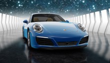
Der Schmale – David Lenaerts’s blog

Flash Platform Experiments

Away3D 4.0 Demo for Flash on the Beach 2011

Tags: , , , , , , , ,

Oh such busy times! I’m not keeping up with my planned blog posts as much as I’d like, but between work and Away3D 4.0 updates there’s not as much time left to actually write about it. But, I did want to share a video from my presentation on Flash on the Beach 2011, showcasing some of the things that can be done relatively easily with Away3D 4.0 by compositing several shadow methods and so on. It also showcases some tricks that aren’t in the engine yet, but will be after some refactoring. It’s very much a coder’s demo, so don’t expect too much artistic sense ;)

Some of the things shown that I’d like the point out:

  • Subsurface scattering for ice and gelatinous materials
  • Large amount of independently moving scene graph objects (1000 cubes)
  • Terrain texture splatting
  • Partial shadow mapping for large view frustra (coming soon)
  • Dynamic cube map refraction + colour aberration (coming soon)
  • Dynamic cube map reflections (coming soon)

I’ll elaborate on some more once they’re available in the engine, I promise! :)

The Away3D team also recently joined forces with Evoflash (in particular Simo) again to create a real scene demo for Adobe MAX. Read all about that one Simo’s blog. Great job guys!

Leave a comment (9 comments)

Building efficient content in Away3D 4.0: Sharing Materials & Geometries

Tags: , , , , , , , ,

Time to dig deeper into Away3D 4.0 and see how you can structure and manage your content to get the best performance! If you haven’t read the previous posts, it wouldn’t hurt to do so now, since this one will be all about Materials (on the Mesh side of things) and Geometries.

In any sort of project, if you have data collections that use a lot of memory, it makes sense not to duplicate them if you want to share the same data across several clients (clients simply meaning “users of the data”). Instead, you make all clients refer to the same data object, or model. Similarly, you probably wouldn’t want to perform the same expensive operations on this data for every client. The shared model can take care of that only once for all clients. In the Away3D scene graph structure, the Geometry is essentially your model, and a Mesh refers to it. Many Meshes can make use of the same Geometry. Similarly, Materials can be shared across Meshes as well. This all sounds very logical, yet for some reason I can’t fathom, this is a principle that’s often violated against. Even though Away3D internally tries to minimize memory use and tries to share things as best as it can (it caches Program3D instances, Texture objects, etc., across material instances), I can’t stress this enough: reuse Material and Geometry instances whenever possible. Not only does it limit CPU and GPU memory usage, it’s also essential for performance. I’ll explain why.

Reusing Materials

Every material uses a “shader program”, which is represented in Actionscript by a Program3D object. It’s a combination of a vertex shader and a fragment shader. I won’t go into the subject of shader programs in detail, but if you’re interested, check wikipedia for starters. A large task of the shader program is to define the colour of every pixel that’s being drawn. In other words, it controls how your rendered object will be coloured, textured, lit, shaded, … If it’s on your screen, it passed through a shader program. As a result, a different material means it needs a different Program3D. When drawing objects, the gpu needs to be told to use a different program every time for every material. Unfortunately, this switch is typically very expensive and something you’d want to prevent as much as possible. To this end, Away3D sorts all the objects that need to be rendered (the so called “renderables”) primarily according to their materials so all objects with the same material will be rendered consecutively. If you’re using different material instances for things that look exactly the same, it means more programs need to be switched needlessly.

Sharing materials allows more renderables (here SubGeometry objects) to be rendered with less switches

Sharing materials allows more renderables (here SubGeometry objects) to be rendered with less switches

Okay, I’ll admit, that isn’t entirely true. For those interested, I’ll explain what really happens. Whenever a material is created or changed so that it needs to create a new shader program, the vertex and fragment code is regenerated. A Program3D is requested from a central cache, but if a Program3D object already exists for that exact code combination, the existing object is returned. Different materials using the same code also use the same programs, which means there won’t be any program switching. However, it’s easy enough to accidentally have small differences between materials so that the code – and in turn the program instance – changes. And the following is still true regardless:

Every time a material changes, certain data needs to be uploaded to the GPU: Textures, lighting properties, … No caching of Program3D objects is going to prevent that. If you use a new material instance for every object, these uploads may occur for every object. Share a material, and it only happens once for all the renderables using it.

Note: if you really need several material instances, but you’re using the same BitmapData objects as textures or normal maps, at least try to share those across materials unless you have a very good reason not to. RAM’s not for wasting! Furthermore, there’s a limit to the amount of Texture objects (a buffer object representing the image data on the GPU) that can be created, and for every BitmapData, a Texture is created. You wouldn’t want to go over the limit!

Reusing Geometries

Similarly, Meshes that use the same data should all refer to a single Geometry instance. A very common example is a game in which there are several occurences of the same monster type spread throughout the game map. You can have one “beer demon” Geometry, and place many beer demons in your level by making the different Mesh objects refer to that single Geometry instance. Not only does this use much less memory, it also causes less instances of VertexBuffer3D to be created (these are buffers representing the vertex data on the GPU side of things). There’s a limit on how many can exist at any given time and if you exceed it, an error will be thrown and your game will crash. Sharing Geometry objects can also result in better performance in some cases, because if the same Geometry was used for the previously rendered object, it may not have to reupload its data to the GPU!

Material/Geometry Tandems

In many cases, especially in games, you’ll have a collection of game object “types”, such as different monsters, a barrel, weapon/health/power-up pick-ups. Each of these objects will probably have their own specific Geometry and Material objects. Makes sense, since you typically wouldn’t want to use a barrel geometry for a monster, or a shotgun texture on a health boost pick-up, would you? This one-on-one mapping is a pretty fortunate situation, because it means that the rendering for these objects can be batched very efficiently. Only when different objects will be rendered, does any material or geometry data need to be uploaded, with the exception of scene-graph-specific data such as transformation matrices.

Rendering objects with one-on-one Material/Geometry combinations

Rendering objects with one-on-one Material/Geometry combinations

Making sure that the same Geometry and Material instances are used across all instances for the same game object type is easy. The Mesh class contains a clone() method that creates a new Mesh instance that refers to the same Geometry and Material. This way, you can build a library of reference Meshes that are not actually added to the scene. Instead, you populate your scene with these clone objects. You can dispose of them whenever they’re picked up (health pack) or killed (monster), while the reference mesh and its material and geometry can be disposed when everything is unloaded. For this reference library, you can use Away3D’s AssetLibrary, which will take care of all your loading and management needs :)

For example

Here’s a comparison:

Demo NOT reusing anything (warning, can be very slow!)

Demo reusing both Geometry and Materials

Source for both

I’ll admit, a large cost in the first demo is the creation of the objects rather than their use. This creation is a constant cost, however, and you can see the performance drop drastically over a short time. So… Enough incentive? :-)


Update

In the “dev” branch (and when we go Beta it will also be in the master branch), BitmapMaterial was removed in favour of TextureMaterial, accepting a texture rather than a BitmapData. It goes without saying that you should share these texture objects whenever possible rather than creating new textures with the same content.

All sources for this post have been updated to use said dev branch: https://github.com/away3d/away3d-core-fp11/tree/dev

Leave a comment (14 comments)

The Away3D 4.0 Scene Graph Architecture 1: Node Types

Tags: , , , , , ,

I’m planning some future blog posts dealing with tips to get better performance out of your Away3D 4.0 (FP11) projects. When working with the GPU, it’s easy to get unexpected slowdowns due to inefficient content. There are a lot of common mistakes and misconceptions that I see popping up time and time again, and I reckon it’s a good idea to try and rid the world of them. Before that, it’s important to understand one of the most central aspects of the engine: the scene graph. It forms the basis of many of the performance tips that will follow, so despite the seemingly trivial nature of the subject, it is important to explain things in proper detail.

The scene graph is essentially the 3D equivalent of the Flash display list. If you’ve worked with Away3D before, or any other 3D engine for that matter, it’s nothing new; every version of Away3D has had a scene graph, even if it was never been called that way, and it’s simply the Scene3D object and all its children: ObjectContainer3D, Mesh, Sprite3D, … It’s the building blocks you use to construct your 3D scene in a hierarchical way that feels natural. There are some differences with older versions of the engine, especially how Mesh objects are constructed, so let’s step through the different objects.

Scene graph objects

The scene graph is made up of objects (nodes) that form a tree data structure. Nodes can be added as a child to other nodes, which makes their transformation (position, rotation and scale) relative to that of their parents’.

  • Scene3D: Essentially, this is the root node of a scene graph. It wraps a root ObjectContainer3D and links it to the spatial partitioning system (more on that in a future post). Whenever a View3D is created, an empty Scene3D is created by default if one is not passed along. Since it’s a root node by design, a Scene3D object cannot be added as a child to other containers.
  • ObjectContainer3D: Comparable to Flash’s DisplayObjectContainer, it is the most basic scene graph node. It can be added as a child to other ObjectContainer3Ds (or subclasses), and in turn it can be a parent of other ObjectContainer3D (or subclass) objects. Despite the name, child nodes aren’t necessarily “contained” by the container in the most literal sense. It merely implies that the child objects’ transformation is relative to that of the parent, much like Flash Sprite objects that are a child of a DisplayObjectContainer. Move or rotate the parent, and the child will move or rotate along. For instance, a rider object can be a child of a horse object so that when the horse moves, the rider will always be in the correct place without having to explicitly update its position. It does not mean – assuming your game is within the bounds of the morally acceptable – that the rider is inside the horse. This may seem like a distinction too trivial to even point out, but it’s a misconception that has managed to confuse a good few people in the past. The results are often wastefully constructed scene graphs and superfluous transformation updates, simply because of this misinterpretation. Every scene graph object that you manipulate to generate your scene (that excludes Scene3D itself), extends ObjectContainer3D.
  • Entity: While it’s an abstract class and you should never use it directly, it’s important enough to know of its existence, especially if you’re looking into creating your own scene graph objects. It forms the base for any object that has a “physical presence”. Entities are collected in the render loop, and are dealt with differently depending on the concrete subclass.
  • Mesh: The most typical renderable 3D object, consisting out of a Geometry that defines vertices, triangles, and all that jazz. It also provides the material with which the object is rendered. Mesh objects will be the central subject of the next blog post, so I’ll keep it brief here.
  • Sprite3D: A so-called “billboard”, basically a 2-triangle plane that always faces the camera. Remember the monsters in old shooters like Doom or Duke Nukem 3D? Sprites, baby!
  • SkyBox: A special case scene graph object, used for faking the sky or environment in a scene. As it’s always supposed to be “as far away as possible”, it can’t be moved and will always center itself around the camera and size itself so it’ll fit within the camera frustum. There’s not supposed to be more than one SkyBox in the scene.
  • PointLight/DirectionalLight: These are light objects that can be used for material shading and casting shadows (DirectionalLight only). Traditionally, lights weren’t part of the scene graph in Away3D, but now they can be added in order to make lights dependent on other objects’ position (fe: the light on a miner’s hat). However, because directional lights are “infinitely far away” to approximate very distance light sources such as the sun, their position is in fact irrelevant. It’s recommended to add them to the scene directly. However, the position in combination with lookAt could be used to create sun cycles, but yeah let’s not go there now ;)
  • Camera3D: Cameras are used to render the scene to a view, and don’t necessarily need to be added to the scene graph (by default, they aren’t). However, it can be convenient if you want to make your camera’s position and orientation depend on another object (a rigid chase camera for instance), which is also a change from older versions of the engine.
SceneGraph

The scene graph inheritance structure (black arrows) and the Mesh/Geometry architecture (white arrows)

See, not that different from what you probably already know! However, the way Meshes are constructed, and how they relate to Geometry objects has changed considerably, and can be an important aspect when creating efficient content. And that’s… for the next blog post!

Leave a comment (3 comments)

Subsurface Scattering and Advanced Skin Rendering in Away3D 4.0 (“Broomstick”)

Tags: , , , , , , , , , ,

skinRenderingMolehill, Adobe’s new API to leverage the GPU for rendering, was made public some time ago in the form of an “incubator” Flash Player release, and along with it we released an early pre-alpha version of Away3D 4.0, codenamed “Broomstick”. I’ve been working on the new engine for quite some time now, and since the release I hadn’t had the time to post any more information aside from what was shown on the blog post. Time to change that, I’d say!
Before you do anything else, you’ll need to install the Incubator Flash Player, because the demos will be using that. Secondly, there’s no guarantee that anything related to Away3D 4.0 will be exactly the same in the final release, as it is of course an early alpha. Finally, source for all demos is in the usual Away3D repository. They’re a bit messy, since they were actually just quick test files to see if everything still works ;)

Subsurface scattering

Subsurface scattering is basically what happens to light when it travels through a translucent surface. Instead of either simply reflecting off a surface or passing through it, the light will enter the material, reflect a good couple of times before exiting the surface again and reaching the eye. This behaviour causes a general blurring of the diffuse lighting on an object and allows light to shimmer through less “thick” regions. Just think about how a candle’s flame shines through the wax.

There’s a few rendering techniques that perform subsurface scattering to some extent. A popular approach is to render the diffuse lighting to a texture and simply blur it subsurfaceDepthMapslightly. However, I find that this approach doesn’t allow light to travel through an object and so I opted for another approach: using depth maps. Similar to shadow mapping, a depth map is rendered from the point of view of the light, and when rendering, we compare depths of the rendered pixel to the value in the depth map. Instead of using this to determine whether a pixel is in shadow or not, we can use the difference between these values to determine the “thickness” of the object, or how far light has to travel through it to be able to reach the eye (see my amateurish schematic on the right :) ).

Depending on this distance, we can colour the pixel differently. We define a colour the light gets by traveling through the object (this depends on the actual material), and the final pixel’s colour ranges from this “scatter colour” to the material’s (texture) colour, depending on how thick it is.

This technique can be used to make materials look like wax, such as in this demo.

Advanced Skin Rendering

Skin is in fact a translucent object, so we can use subsurface scattering to increase the realism, as usual rendering techniques often create a harsh or clay-like effect. Instead, subsurface scattering softens the general shading and allows light to travel through more translucent regions such as the ears, softer parts of the nose, etc.
To further increase the realism, the specular highlights are modulated using a fresnel term. As with most objects in reality, the reflectivity of an object changes depending on the view angle, and with it the strength of the highlights. When observing skin head-on, there’s usually not a strong direct light reflection, but it can usually be perceived on shallow angles.
The result of both can be seen here.

In Away3D 4.0

First of all, to get started using Broomstick, check out this article by John Lindquist. He did a great job explaining how to get started!
Default materials in Away3D 4.0 are currently implemented using “methods”, which are properties of a material that define how the shaders work in a modular fashion. This way, there’s no need for a billion variation of Material classes for each combination. For subsurface scattering, we need to change the diffuseMethod property of a material and assign an instance of SubsurfaceScatteringDiffuseMethod. For the fresnel specular highlights, we assign an instance of FresnelSpecularMethod to the specularMethod property. It’s all in the source, so knowing this, you should be able to make sense of what’s going on in there :)

Demos

In case you skipped through the rest of the article, here’s a demo recap. Loading times may be long, as the models are pretty big :)

Wax Statue : Illustrating subsurface scattering to generate a material resembling wax.
Head rendering: Using subsurface scattering and a specular fresnel term to increase realism in skin rendering. Press any key to toggle the subsurface scattering, so you can see the difference. Note the light shining through the ears, for example.

Leave a comment (2 comments)

Hacking the Lite pt.2: Fake Shadow Mapping

Tags: , , , , , , , , , ,

fakeShadowsSince I’ve been working on Away3D 4.0 (Broomstick) for the past few months, it was pretty hard to find the energy to keep this blog up to date, and the promised part 2 of Hacking the Lite kept getting delayed. And delayed. And then delayed some more. Having access to the GPU also caused some debate on whether this series would still be relevant enough. However, after looking at my initial goals for it, I decided it is. After all, the idea was to inspire people to start playing around, and to get people to think in terms of using shaders. Most of the concepts outlined here can be used in Molehill as well. And of course, it’s still some time before we can use the GPU in actual commercial projects ;) So on with the show! This part of the series will build heavily upon the previous part, so it’s perhaps a good idea to review that again.

Shadow maps

Casting shadows is often done using shadow maps. In this case, we’d render a “depth map” of the scene from the light’s point of view. This way, we have a texture containing the distances to the objects closest to the light for every projection ray (which is a single pixel in the shadow map). When rendering the scene, we project every point we are rendering to that shadow map. We can then compare the depth value of the point-to-be-rendered with the value in the shadow map. If it is further away from the light, it must be in shadow and should not be lit. This approach works well, but for current versions of Flash, it’s not very feasible. But, since we’re hacking, there’s other options!

Augmenting projective texture mapping

fakeShadowMapping_thumbIf you take a look at the schematic on the left (click to enlarge), showing where a shadow should fall, you can see it’s much like projection mapping. The sphere is being perspectively projected unto the floor plane with the light as the projection’s origin. This is the exact same projection that projects the light texture onto the objects. As you can see, if we project the sphere onto the light’s texture first, and project that in turn to the floor, the shadow region remains the same. As a result, we could actually simply project and draw the sphere into the light map before it is applied to the floor.

Order and form

shadowOrderTo render a scene with multiple objects, we have to take care to render things in correct order. We need to draw the objects closest to the light first, because they will obviously be casting shadows on object further from the light. Starting out with a clean light map (ie.containing no shadows), we project it on the closest object and then draw that object’s shadow into the light map. Move on to the second closest object, light it, and draw the shadow again. And so on until the last object was reached.

That works great for convex objects, as long as they don’t intersect. For concave or intersecting convex objects, it’s possible that object A casts shadows on object B as well as the other way around. Since we’re rendering everything in a strict order, that’s simply not a possibility. However, this error should generally be acceptable. Another problem is self-shadowing for concave objects, which is impossible using this “cheat”.

Demo and source

Fake shadow mapping demo: really just an adapted version of the previous one.

The source is again on Google Code!

Leave a comment (2 comments)

Speaking at FFK 2011 @ Cologne

Tags: , , ,

ffk11For those living near Cologne, Germany, I’m stoked to announce I’ll be speaking at FFK (FlashForum Konferenz) this year. I’m particularly excited, as last year’s edition is still one of my best experiences in 2010, even though a certain Eyjafjallajökull caused an interesting aftermath for many :-) . Titled “Keeping it Real”, the session will mainly revolve around mimicking reality using real-time computer graphics. So expect a lot of experiments that’ll hopefully show that beauty’s perhaps not always in the entirely abstract!

What’s more, apart from a session, my good friend Frank Reitberger and I will be co-hosting a workshop “Das Efx” on Thursday. It’ll be all about playing around with graphics and 3D rendering, ranging from relative basics to more advanced topics. So if you’re into this stuff, but don’t really know how to get started, be sure to come!

Finally, the next part on Hacking The Light is still in the works. Sadly, there’s a lot that keeps me distracted in the meanwhile, so hang in there! :)

Hope to see you at FFK!

Leave a comment (4 comments)

Hacking the Lite pt.1: Projective Texture Mapping

Tags: , , , , , , , ,

projectiveExciting times afoot! In the not too distance future, we’ll finally get what we’ve been nagging about! I’m of course talking about Molehill, the new hardware-accelerated API Adobe is working on. If you’re curious what we’re doing with Away3D, take a peak at the demo we did with the guys from Evoflash for Adobe MAX. Old news, I know. Moving on.

All that and more is still some time in the future, and in the meanwhile we need to make do with what we currently have available. As part of a session at AUG XL and FlashPlatform, I gave some examples of what we currently can do with Away3D Lite if we’re willing to get our hands a bit dirty. As examples I explained some effects I did for the Spiral Out demo. Now, it’s time to clean up the code mess and explain a thing or two to a slightly broader audience :)

Basically, what I’ll do is show some things that involve making assumptions that prevent the code from being scalable (ahhh… you got me… that’s just a nice way of saying I’m cheating!). The first step isn’t actually cheating at all, and it’s an old and pretty standard shading technique. However, we’ll need this for part 2 in which we’ll do nothing but cheating, and since no one ever seems to do shaders in Lite I thought it’d be a good way to get started.

This it what we’ll end up with. Not the most attractive demo, but it’ll do. Lengthy explanations ahead, for which the source can come in handy (under examples/projectionMapping) :)

Projective Texture Mapping

projectiveDetailProjective texture mapping, as the name clearly suggests, is a texture mapping technique that mimics a light projecting a texture on objects in the scene (think of a projector slide, a lamp shade’s projections on the walls, …). As I said, there’s nothing new or special about this; it’s been done countless times before. The picture on the right pretty much shows all there’s to it (click to enlarge).

Essentially, we place the “light texture” in front of the light. All we need to do, is draw a line from the position we’re currently shading (the “target point”) to the light (the “source point”) and figure out where that line intersects the plane. Grab the light texture’s colour at that position and multiply it with the object’s base texture colour to get the final shaded colour. We can also incorporate additional shading calculations, particularly normal mapping.

Exactly how we calculate the intersection is up to you. You can do a line-plane intersection calculation, or you can – surprise surprise – use a perspective projection matrix to project the target point onto the texture. So rather than projecting the texture onto the object, we’re effectively projecting the object on the texture first. The latter approach is much more flexible and intuitive, since it’s exactly how a camera projection works (in part 2, we’ll see that this will come in handy too).

Shading in Away3DLite

Away3DLite, minimal as it is, has only very limited support for shading. There’s a Dot3BitmapMaterial that no one seems to know about, though, courtesy of Mr. Bateman ;) I recommend taking a look at that code, just to see how you could implement a custom shader. At a minimum, all you’d need to do is extend BitmapMaterial and override the updateMaterial method (don’t forget to include and use the namespace arcane). In there, you can do anything you like as long as you end up passing a valid BitmapData object to the _graphicsBitmapFill.bitmapData property. For shading purposes, it’s best to keep a second BitmapData object to which we’ll be rendering the shaded version of the texture, leaving the original _bitmap object intact for subsequent frames. Of course, for any advanced shading on BitmapData objects, Pixel Bender is king, so we can run a ShaderJob in there.

Taking a look at the source for the ProjectiveTextureMaterial, that’s pretty much exactly what is happening, with one difference. We’re exposing a manual update method rather than overriding updateMaterial. This seems rather odd (and in this particular case it is) but we’ll need that next time (remember, we’re hacking anyway) ;)

There’s of course a final caveat, in that we don’t have any position information since we just have a bunch of BitmapData objects, no actual geometry. And that is of course something essential if we want to do any projecting at all. For that we can take the same approach as the Away3D Pixel Bender shaders do: position maps. Whereas a normal map encodes the normal for every texel, a position map encodes the object position at that point. In Away3D, the pixel shaders generate a position map automatically from the geometry when a material is created, but in Lite, we’ll settle for creating them manually. This actually makes it possible to add details from a height map, providing the shader with much more detailed topological information than what would have been generated from a bunch of triangles. As a result, the projected map can be subtly displaced as it would on a real uneven surface. It’s not very hard to create position maps procedurally (which is part 3) if you keep in mind that xyz maps to rgb and 0×00-0xff for each colour channel maps to the minimum and maximum bounds of the respective coordinate (so where x == minX, r would be 0).

Demo and source

To see the effect in action, check out the demo. Move the mouse to move the projector, click and drag to move the camera, and use the mouse wheel to move the projector closer or farther from the scene. There’s also a small projection avatar floating around that shows to position and orientation of the projector.

Source can be found in my repo at Google Code.

A long post, which I hope is useful for people. If not, let me know and I’ll keep it more concise next time! :)
And oh yes, happy New Year’s!

Leave a comment (6 comments)

Marching Cubes using Pixel Bender: Metaballs / LoFi 4D Julia Set

Tags: , , , , , , , , , ,

juliasetAs promised in my previous post, I would elaborate on some of the things done for the demo. So I’m taking a quick break from work to get this post done :)

Marching Cubes

One thing I did was implement a marching cubes algorithm using Pixel Bender, which is a way to triangulate an isosurface in a scalar field. I had started to write up a whole explanation, but realized it was kinda pointless, as it has been covered plenty of times :) If you’re interested, you’re better off reading up about the subject starting here and here.

Pixel Bender

I know there’s plenty of marching cube implementations in ActionScript out there, but I haven’t seen one using Pixel Bender, so I thought I’d give it a try. I’m using it to calculate the values in the scalar field (at least on the marching cube’s grid corners), and to build the pattern ids needed for triangulation. The benefit of using Pixel Bender is that you can put in any kind of calculation that outputs scalar values, some of which you wouldn’t dare to put ActionScript through. The drawback is that it seems to have some precision problems while doing comparisons (or so it seems), so there’s some missing triangles on occasion.

No transforms, no sorting

Something I’ve realized that’s pretty neat about this algorithm is that you don’t actually need sorting. As long as you make sure the grid is aligned to the “camera” at all times, the triangulation occurs back to front and will already be correctly sorted. This of course means you can’t do any rotations on the triangles, but that’s no big deal. You can simply perform the transformation on the grid coordinates, and let the correct values be calculated for those points. Added bonus, you can do any scaling and translations together with the projection matrix in one call to Utils3D.projectVectors, annihilating the need for any calls to Matrix3D.transformVectors. Result: some extra fps.

Metaballsmetaballs

Metaballs are probably the most iconic example of isosurfaces out there (bar MRI and CT imagery). It was actually my test data for the MC system, but it ended up making a sneaky appearance in the demo (which I still consider a tribute to the undisputed king of ActionScript sticky substances ).

> Metaball demo (click to change textures)

Quaternion Julia Set

Another example I did was to triangulate a quaternion Julia set, which seems pretty popular lately ;) It definitely looks better raytraced, but I couldn’t resist! I’m using the distance estimator function to produce the grid values (see here), and an epsilon distance as the surface’s isovalue. Since things always look less crap with music, I added some for a change.

> Quaternion Julia Set Demo (might take a while to load the mp3)

Source

The marching cubes thingy, as well as the metaballs example source is up for grabs at Google Code . Enjoy! If you make any surfaces with it, I’d love to see them :)

Leave a comment (11 comments)

More Fresnel fun in Away3D: through the looking glass

Tags: , , , , , , , , , ,

glassBallAs a continuation of an earlier post, here’s a variation of the Fresnel Pixel Bender material. Still obviously inspired by Bartek‘s Unity3D shader, it became a glass material with support for chromatic aberration (what causes the rainbow effect in refracted light). The result could come in handy in some situations, so I thought I’d share and commit it to the Away3D trunk as the GlassMaterial.

The material uses the same environment map to do (fake) refractions and reflections, so it’s not actually refracting the real scene around it. However, if you make a sphere map rendering of your scene, the effect can be convincing enough.

The demo shows a couple of default primitives and several settings of the material (such as glass colour and reflection strength), and also uses a new primitive called TorusKnot (which is a (p,q) torus knot). Consider that a tribute to a demo shown by Ralph during his presentation at FITC Amsterdam ;) . Click to cycle through the different settings, and check the source to see how it all works.

Update: As Makc pointed out in the comments (and rightly so), the refraction looked rather icky, so I updated it that it uses linear sampling. It’s a bit slower but looks much better.

Leave a comment (6 comments)

BSP/PVS released in Away 3.5.0!

Tags: , , , , , , ,

bsppvsToday, we’re happy to announce the release of Away3D 2.5.0 and 3.5.0. Along with other features and changes, of which you can read more in the official announcement, it contains the new BSP/PVS support! I’ve slaved months on this, so I’m glad it’s finally made public! Keep in mind that we’re always improving it, so it’ll only get better from here :-) So what’re all these abbreviations about?

(Warning: a long-winded post ahead. If you’re not interested in the details, stick to the official announcement!)

Binary Space Partitioning

BSP is a scene graph that divides a static scene up by splitting it recursively along planes into two half-spaces. If after splitting, the geometry in that subspace is convex, no further subdivisions are needed. In the end, we have a binary tree containing convex meshes at the leaves. What’s the use, you may ask? Well, since all the parts are convex, we don’t need to do any per-triangle sorting. By correctly traversing the tree and rendering the parts in the right order, the sorting is faster AND 100% correct. Specifically for Flash 3D, that means we don’t need to subdivide triangles to try and resolve z-fighting. Furthermore, it also greatly speeds up frustum culling and collision detection. This only works for static scenes however. There are dynamic bsp trees, but they don’t support the biggest speed-up, being the PVS.

Binary Space Partitioning on Wikipedia

The Potentially Visible Set

bsppvs2When we have a static BSP, we can use this data to determine which leaf nodes are visible from any given leaf node. This dataset is called the PVS (Potentially Visible Set). It allows us to prevent most of the occluded geometry from being rendered (which, usually, is most of the total geometry). Needless to say, this can lead to huge speed improvements. It’s the same technique games such as Quake, Half-Life, Unreal, … used. However, this speed improvement comes at a price (or what did you think? :) ), which is explained in the “Building” section of this post.

This little bastard was a pain to do. It’s the reason days turned to months of my evenings to get right, and I definitely couldn’t have done it without the help from this thesis: View Space Linking, Solid Node Compression and Binary Space Partitioning for Visibility Determination in 3D Walk-Throughs by Joel Anderson. Also, props to Joa for giving me some optimization tricks and food for thought!

Potentially Visible Set on Wikipedia

Building

Fabrice did a great job implementing the BSP/PVS builder into Prefab3D, so you can bake your lighting and generate the BSP/PVS as AWData in one programme. When compiling a model with PVS, there’s some guidelines you should keep in mind. No, let’s call them rules instead. Not obeying these could result in the build getting stuck, poor collision detection, or some random unpredictable results.

  • bsppvs3Your model must be completely “sealed”. No leaks into “nothingness”! This is important because the PVS would try to find visible data from that leak and get stuck.
  • Work on a grid. Make sure your vertices are snapped to a grid which is not too coarse. If not, the BSP splitting could create triangles that are too small, causing havoc in the form of floating point errors, too small triangles, inefficient splits, etc…
  • Try to occlude a lot. Don’t make too much geometry visible from any part of the model. This speeds up the model during rendering as well as the PVS build.
  • Axis-aligned walls/ceilings/floors work best. They’re fast to do calculations on and if you model somewhat smartly, they form a better “space splitter”.
  • Sometimes it’s good to keep small details out of the BSP geometry, and add them using the regular addChild method as this keeps the trees cleaner and more efficient.

Finally, there’s a LOT of settings, but you should probably not have to mess too much with them unless you really know what you’re doing. Soon, we’ll have some proper tutorials explaining the nitty-gritty of building (and we might have some other tools to make things easier on you).

Check the video showing a build in action!

Demos

  • The Hacienda Experiment (Beta): Fabrice and I created this for Adobe’s keynote at FITC Amsterdam in a very limited amount of time, before the BSP functionality was even finished. Lots of stress and insecurities, building the AWData exporter, etc. So, forgive us if there’s still some bugs in this version ;-) (If you get stuck, jumping out using the space bar usually does the trick ;-) )
  • Bunker Demo: Made by Fabrice to illustrate how easy it is to export BSP/PVS data from Prefab3D (see video mentioned before). It also shows how fast it can run with good occlusion. (Check the source)

Thanks for sticking around for such a long post, but hey, with the amount of work gone into this, I reserve the right to bore you to death with it! ;-)

Leave a comment (17 comments)

© 2009 Der Schmale – David Lenaerts’s blog. All Rights Reserved.

This blog is powered by Wordpress and Magatheme by Bryan Helmig.